MARGセンサーから三次元姿勢推定!(Processingで3D表示?編)

Processing 3
先日使ったMARGセンサー(xyz角速度・xyz加速度・xyz地磁気の計9軸)から得られたデータを元に、相補フィルターの一種Madgwickフィルターを通してドローンの現在の姿勢を推定する実験中です。
得られた情報は「Processing 3」を使ってリアルタイムに3Dオブジェクトに反映させたいのですが、いきなりプログラムを作るのも大変なのでNETで検索した所「MadgwickAHRS/extras/Visualizer/Visualizer.pde」と言う少し手を加えれば使えそうなプログラムを発見しました!

1. 実物と3Dモデルが連動?
やりたい事の流れは以下①~⑤の通りです。
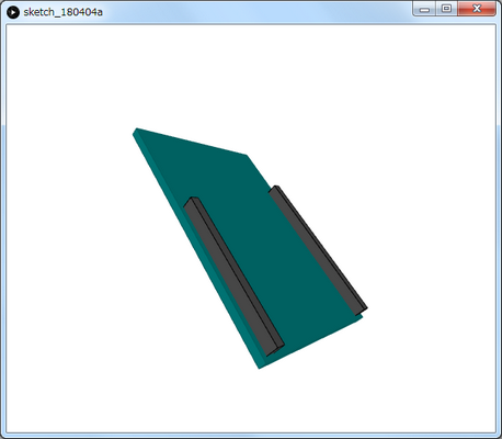
見つけた図1のプログラムでは⑤の処理を行います。
①「MARGセンサー」が動く
②「加速度・角速度・地磁気」データ送信
④「3D姿勢データ」送信
⑤「Processing」で3Dモデルの動きに反映です!

import processing.serial.*;
Serial myPort;
float yaw = 40.0;
float pitch = -50.0;
float roll = 0.0;
void setup()
{
size(600, 500, P3D);
// if you have only ONE serial port active
myPort = new Serial(this, Serial.list()[0], 9600); // if you have
only ONE serial port active
// if you know the serial port name
//myPort = new Serial(this, "COM5:", 9600); // Windows
//myPort = new Serial(this, "/dev/ttyACM0", 9600); // Linux
//myPort = new Serial(this, "/dev/cu.usbmodem1217321", 9600); // Mac
textSize(16); // set text size
textMode(SHAPE); // set text mode to shape
}
void draw()
{
serialEvent(); // read and parse incoming serial message
background(255); // set background to white
lights();
translate(width/2, height/2); // set position to centre
pushMatrix(); // begin object
float c1 = cos(radians(roll));
float s1 = sin(radians(roll));
float c2 = cos(radians(pitch));
float s2 = sin(radians(pitch));
float c3 = cos(radians(yaw));
float s3 = sin(radians(yaw));
applyMatrix( c2*c3, s1*s3+c1*c3*s2, c3*s1*s2-c1*s3, 0,
-s2, c1*c2, c2*s1, 0,
c2*s3, c1*s2*s3-c3*s1, c1*c3+s1*s2*s3, 0,
0, 0, 0, 1);
drawArduino();
popMatrix(); // end of object
// Print values to console
print(roll);
print("\t");
print(pitch);
print("\t");
print(yaw);
println();
}
void serialEvent()
{
int newLine = 13; // new line character in ASCII
String message;
do {
message = myPort.readStringUntil(newLine); // read from port un
il new line
if (message != null) {
String[] list = split(trim(message), " ");
if (list.length >= 4 && list[0].equals("Orientation:")) {
yaw = float(list[1]); // convert to float yaw
pitch = float(list[2]); // convert to float pitch
roll = float(list[3]); // convert to float roll
}
}
} while (message != null);
}
void drawArduino()
{
/* function contains shape(s) that are rotated with the IMU */
stroke(0, 90, 90); // set outline colour to darker teal
fill(0, 130, 130); // set fill colour to lighter teal
stroke(0); // set outline colour to black
fill(80); // set fill colour to dark grey
box(170, 20, 10); // draw pin header as box
box
box(210, 20, 10); // draw other pin header as box
}

2. まとめ

励みになりますのでよければクリック下さい(^o^)/
